It’s fair to say that electronic prototyping and the creation of custom hardware at home has exploded over the past few years. As a developer, the idea of combining my programming skills with electronics to create a physical object is intoxicating.
But where do you begin?
Arduino has become synonymous with electronic prototyping (For example, the prototype for the original Pebble smart watch was built with an Arduino). Its pretty much the go-to platform as an entry point into this exciting world.
There are companies making this even easier by producing kits that contain all of the components necessary to get started. I happen to own one such kit (a present from my wife a couple of years ago) – the DIY Gamer Kit from Technology Will Save Us. Kit in hand; I set out to make something…

Building the Gamer
The DIY Gamer Kit is a lovely thing. The packaging is great and the components are all interesting and shiny. You get all sorts of stuff:- Buttons, switches, a light sensor, LED’s, an infrared transmitter and receiver, a buzzer, an 8×8 pixel screen. Honestly, just spreading out the components is enough to get you excited. Here, see what I mean…

You will need a few other things. You may have these – I did not and, with UK high street prices being the way they are, they set me back another £40 or so. Basically a soldering iron, solder, wire cutters, a flat-head screwdriver, Blu-Tack, a 9v battery, and a de-solder pump. You could probably get away without that last item if you’re careful but its useful if you do mess something up.
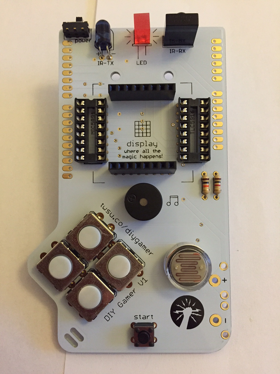
You start with the printed circuit board which has pre-punched holes for the components. You just pop the components in, solder them on the back, and snip off any excess.


The finished item a few hours later. You can see the Arduino plugged into the circuit via header pins on the back. The 64 pixel screen is also plugged in. The whole thing is fairly solid. The battery connections are a bit of a pain and result in a setup where the battery just sort of hangs in place. I’d have preferred some sort of bracket in the plastic housing and a snap connector.

There is some plastic housing provided to protect the components. You can see it attached here. This was one of the trickier steps as it uses nylon nuts and bolts which are incredibly fiddly and unfortunately easy to cross-thread. The final kit does look rather nice though :)

Writing Some Code
With the Gamer complete, its time to write some code. Technology Will Save Us provide their own library to interface with the Gamer Kit. It doesn’t do a whole lot, just provides some convenience methods for you but is useful nevertheless.
The Arduino IDE utilises the Wiring framework which itself is based upon the processing programming language and tooling. The best reference for it is directly on the Arduino website here.
Technology will save us provide a handful of sample programs too which are very helpful and where you will learn the most.
I quickly cobbled together a very simple program intended to display a ball with a basic bouncing animation. The code is very simple and I’ve also uploaded it to GitHub here.
#include

Gamer gamer;

byte bounce1[] = {
  B00000000,
  B00011000,
  B00011000,
  B00000000,
  B00000000,
  B00000000,
  B00000000,
  B00000000
};

byte bounce2[] = {
  B00000000,
  B00000000,
  B00011000,
  B00011000,
  B00000000,
  B00000000,
  B00000000,
  B00000000
};

byte bounce3[] = {
  B00000000,
  B00000000,
  B00000000,
  B00011000,
  B00011000,
  B00000000,
  B00000000,
  B00000000
};

byte bounce4[] = {
  B00000000,
  B00000000,
  B00000000,
  B00000000,
  B00011000,
  B00011000,
  B00000000,
  B00000000
};

byte bounce5[] = {
  B00000000,
  B00000000,
  B00000000,
  B00000000,
  B00000000,
  B00011000,
  B00011000,
  B00000000
};

byte bounce6[] = {
  B00000000,
  B00000000,
  B00000000,
  B00000000,
  B00000000,
  B00000000,
  B00011000,
  B00011000
};

byte* frames[6] = {bounce1,bounce2,bounce3,bounce4,bounce5,bounce6};
int initial_volume = 5;
int initial_speed = 300;

void setup() {
  gamer.begin();
}

void loop() {
  int min_frame = 0;
  int volume = initial_volume;
  int speed = initial_speed;
  for(int max_frame=0; max_frame<6; max_frame++) {
    for(int x=max_frame; xmin_frame; x--) {
      gamer.printImage(frames[x]);
      delay(speed);
    }

    min_frame++;
    speed=speed-(min_frame*20);
  }
  delay(1000);
}

void beep(int duration) {
  digitalWrite(BUZZER, true);
  delay(duration);
  digitalWrite(BUZZER, false);
}
I certainly plan on exploring some more of the Gamer’s capabilities and writing some more significant code. Who knows, it may eventually lead me into building my own circuits :)
(A quick note about Technology Will Save Us: I actually had a bit of a false start with this kit as it didn’t initially work. A few email exchanges with the guys at TWSU to diagnose the issue and they ended up replacing the kit – very kind of them and they were very pleasant through the whole thing :) )